
Test the coil, operating circuit and mechanical response—not just the click
Test W220 starter and 722.6 transmission solenoids with resistance and voltage-drop checks, component-specific values and clear stop points.
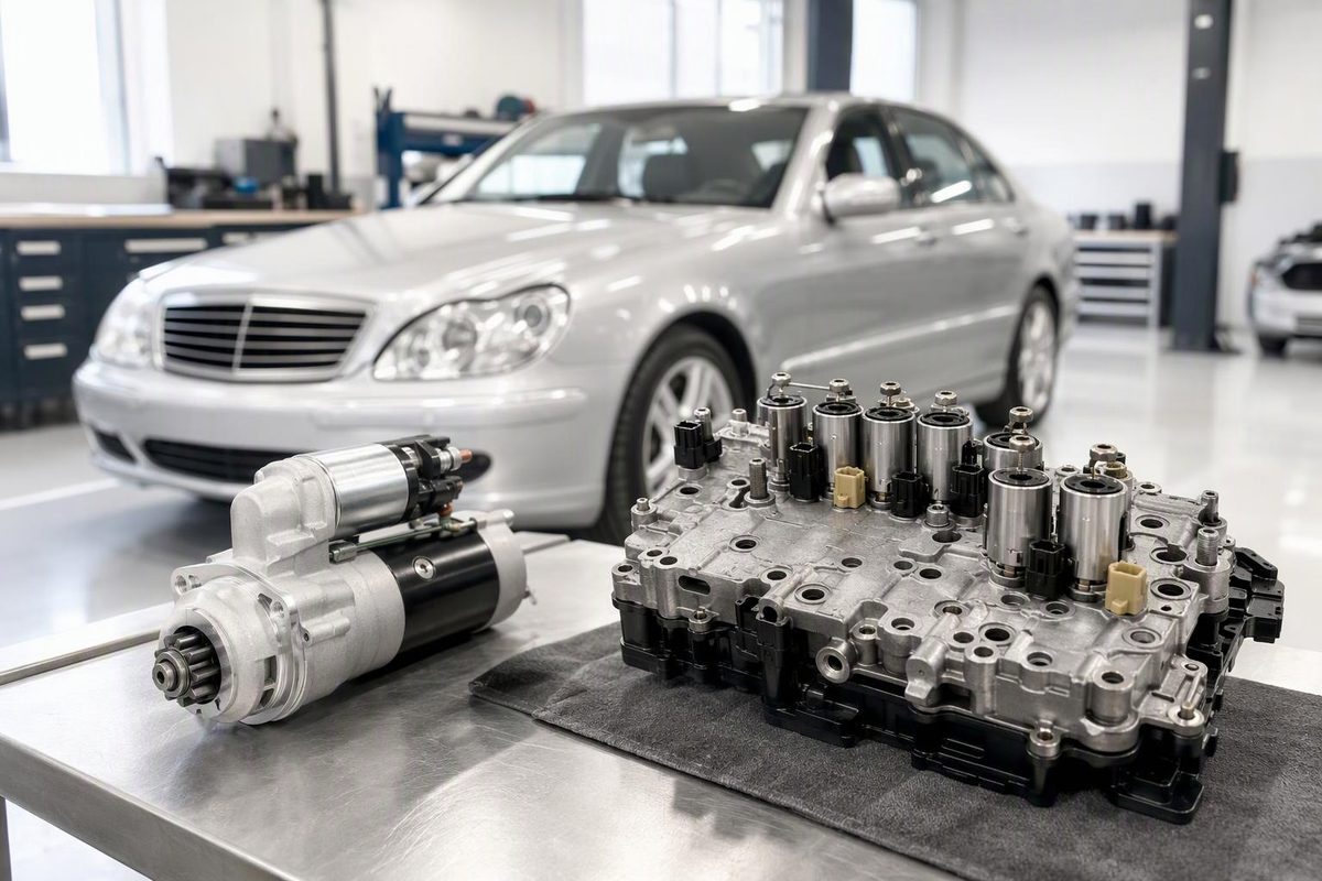
A useful solenoid test checks three things: coil resistance with power off, voltage and ground while the circuit is operating, and whether the commanded action actually occurs. A click only confirms that something moved. A normal resistance reading only shows that the winding is not obviously open or shorted.
First identify the component. A W220 starter solenoid and a 722.6 transmission solenoid have different circuits, resistance values and test methods. Record the VIN, model year, engine, transmission designation and component part number before looking up specifications.
1. Scan before disconnecting anything
Save fault codes and available event or freeze-frame data from the module that controls the circuit. A basic engine-code reader may not communicate with the W220 transmission, suspension and body modules.
A code naming a solenoid circuit does not prove that the solenoid has failed. Possible causes include an open wire, poor connector contact, missing supply, excessive circuit resistance or a control-module fault. For a shifting complaint, preserve this evidence before following the wider automatic-transmission diagnostic sequence.
2. Measure coil resistance with power off
- Switch off the ignition and isolate the circuit according to the vehicle wiring information.
- Unplug the solenoid or the connector through which it will be measured. A connected module can create a parallel electrical path and a misleading reading.
- Select the lowest suitable resistance range on the multimeter.
- Touch the probes together and note the test-lead resistance. This matters when checking a low-resistance transmission solenoid.
- Measure across the coil terminals. Subtract lead resistance unless the meter compensates for it.
- Compare the result with the specification for that exact component at approximately the same temperature.
An OL or infinite reading usually indicates an open coil or connection. A result substantially below specification can indicate shorted windings. A result within range permits further testing; it does not prove that the valve moves freely or that the winding remains sound when hot.
For an isolated two-wire solenoid, also check from each terminal to the metal housing. There should normally be no continuity to the case. Do not apply this rule to a one-wire design intended to ground through its housing.
3. Test the operating circuit under load
Reconnect the circuit and back-probe only where the applicable service procedure permits. Operate or command the component, then check:
- voltage at its supply terminal;
- voltage drop between battery positive and the solenoid supply;
- voltage drop through its ground or controlled side;
- commanded state or duty cycle with a capable scan tool.
The circuit must carry current during a voltage-drop test. An unloaded wire can show battery voltage through a poor connection and then fail to operate the load. Fluke’s automotive guidance explains why a voltage-drop test can reveal restrictions that an ohmmeter misses.
Do not use an incandescent test lamp on an unidentified control-module output. Do not feed battery voltage into an unknown terminal. Some solenoids are pulse-width controlled, and a jumper can damage the controller or overheat a low-resistance coil.
Testing a W220 starter solenoid
For a no-crank complaint, select Park, apply the parking brake and keep probes, clothing and hands clear of moving parts. Do not bridge the starter’s large terminals.
- Confirm that the battery is charged and its terminal connections are secure.
- Check for the start command at the starter-solenoid control terminal while the key is held in Start.
- Perform positive- and ground-side voltage-drop tests during the attempted crank.
As general—not Mercedes-specific—limits, Fluke gives approximately 0.3 V on the positive side and 0.2 V or less on the ground side, with an acceptable combined drop of 0.2–0.5 V. Its starter voltage-drop procedure measures between the battery posts, starter stud and starter housing while the circuit is loaded. Use Mercedes specifications if the applicable service information gives different limits.
The results determine the next step:
- No start command: diagnose the start-authorisation circuit, control circuit and wiring upstream.
- Excessive cable voltage drop: repair the affected cable or connection before condemning the starter.
- Correct command and acceptable high-current paths, but no engagement: suspect the starter/solenoid assembly after confirming that the engine can turn.
A click without cranking is not a conclusive solenoid diagnosis. Burned high-current contacts, a weak battery, cable resistance, a seized starter or an engine that cannot rotate can produce a similar result.
Testing the W220 722.6 transmission solenoids
Use the following information only after confirming that the car has a 722.6 five-speed automatic transmission. With the ignition off and the transmission circuit disconnected, the solenoids can be checked through the 13-pin case connector. The common supply is terminal 6; the ATSG 722.6 manual identifies the individual solenoid control terminals.
The febi 722.6 conductor-plate guide gives these nominal values:
| 722.6 solenoid | Case-connector terminals | Nominal resistance |
|---|---|---|
| Line-pressure modulation | 2 and 6 | 5.5 Ω |
| 2–3 shift | 8 and 6 | 4.5 Ω |
| 3–4 shift | 9 and 6 | 4.5 Ω |
| Shift-pressure modulation | 10 and 6 | 5.5 Ω |
| Torque-converter clutch modulation | 11 and 6 | 2.7 Ω |
| 1–2/4–5 shift | 13 and 6 | 4.5 Ω |
Account for meter-lead resistance and compare readings taken at similar temperatures. Testing through the external connector includes the solenoid, conductor plate tracks and contacts. It can establish that a circuit is abnormal, but it cannot by itself identify which internal part has failed.
Do not remove the transmission pan merely because a code names a solenoid. First inspect the 13-pin connector for ATF intrusion, damaged terminals or corrosion, verify the supply and external wiring, and review commands and transmission behavior with a Mercedes-capable scan tool. The febi guide notes that failed guide-sleeve seals can allow oil into the harness connector and contribute to short circuits.
Several abnormal solenoid readings can indicate a shared supply, connector or conductor-plate problem rather than simultaneous failure of several coils. Conversely, a coil that reads correctly can still operate a sticking hydraulic valve, suffer an intermittent heat-related fault or fail to produce the expected pressure change.
A solenoid therefore passes only the initial electrical checks when its resistance is correct and its supply and control circuit work under load. It passes the functional test only when commanding it produces the expected mechanical or hydraulic response.