
A Turbine Speed Code Does Not Automatically Condemn the Conductor Plate
Diagnose W220 722.6 turbine-speed faults with module codes, N2/N3 live data, connector checks and fluid inspection before replacing the plate.
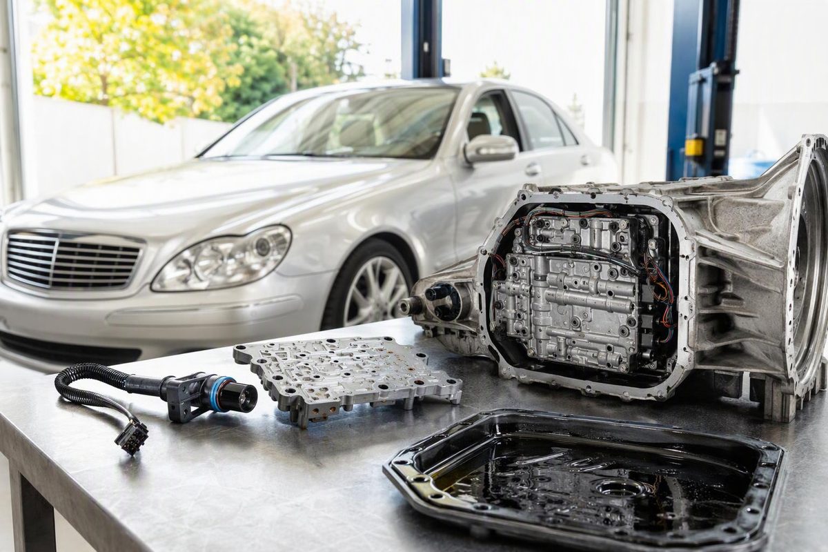
On a Mercedes-Benz W220 with the 722.6 five-speed automatic, the “turbine speed sensor” is not an external sensor that unscrews from the case. The transmission uses two internal Hall-effect speed sensors, N2 and N3, built into the conductor plate above the valve body. A confirmed internal sensor failure normally calls for a conductor-plate replacement, not a replacement transmission—but a generic P0715 alone does not confirm that failure.
Select the evidence you have; the result shows the next justified step.
Is Conductor-Plate Replacement Supported?
Choose the closest findings from the scan, live data and external circuit checks.
Read the Mercedes transmission module, compare N2 and N3 in the gears where each signal is expected, and check the shared circuits and 13-pin connection before ordering a plate.
Source: diagnostic relationships from the ATSG 722.6 service manual and Febi conductor-plate guide.
Confirm the Installed Transmission Is a 722.6
Identify the gearbox before buying parts. The full transmission designation is marked on a raised area on the left side of the case. Different 722.6 versions use different internal ratios and clutch capacities, so ATSG warns that correct identification matters when exchanging units or internal parts (ATSG 722.6 service manual).
Use the VIN and complete designation—such as 722.6xx—when checking parts and service information. This matters particularly when the car’s repair history is uncertain. A W220 badge, model year or online parts-list match is not as reliable as the number on the installed transmission.
N2 and N3 Do Not Report in Every Gear
The 722.6 does not measure input speed directly in every operating condition. N2 monitors the front sun gear, while N3 monitors the front planetary carrier. The transmission controller uses those signals to calculate input speed. Both sensors are part of the conductor plate (ATSG).
The expected signals change with gear:
- In second, third and fourth, N2 and N3 should report the same input speed.
- N3 is not reported in first or fifth.
- N2 is not reported in Reverse.
A zero or mismatch is meaningful only when the relevant signal should be present. Persistent N2/N3 disagreement in second through fourth can result from an electrical signal fault, but it can also indicate a real internal speed discrepancy.
Some faults leave the transmission in its current gear and then put it into hydraulic limp mode after the vehicle stops and the engine is restarted. Depending on the application, the available forward gear may be second or third, with Reverse remaining available. ATSG also identifies improper-ratio and input-sensor-overspeed faults as conditions that can cause loss of Drive (ATSG).
Save the Transmission Codes Before Clearing Them
Use a scan tool that can enter the Mercedes ETC/EGS transmission module, not only a generic engine-code reader. Record:
- Current, stored and intermittent transmission faults
- Freeze-frame or event data, where available
- N2 and N3 actual speeds
- Selected and actual gear
- Engine speed and wheel-speed data
- Transmission-fluid temperature
- System voltage
P0715 is a generic input/turbine-speed circuit code, but the transmission module can provide more useful component detail. Published 722.6 code documentation separately identifies N2, N3 and RPM-sensor supply faults (722.6 fault-code list).
Wording varies with controller generation and scan-tool translation. Work from the complete module report rather than the five-character generic code alone.
Check Voltage and Shared Circuits Before the Sensor
Test battery condition and charging performance. If the scan contains voltage faults or several unrelated electrical faults, verify the transmission controller’s power and grounds before diagnosing an internal sensor.
N2 and N3 share a sensor-voltage supply and sensor ground. If both speed signals disappear together, check those common circuits before condemning the conductor plate. Simultaneous signal loss is less consistent with one independently failed sensor than an abrupt loss of one signal while the other remains plausible.
Inspect the 13-Pin Connector and External Harness
Look for an external ATF leak at the transmission connector sleeve. Disconnect the plug and inspect for fluid, damaged pins, corrosion and poor terminal fit. Follow the harness and inspect the transmission-control-module connectors for migrated fluid.
The sleeve’s seals can leak. Febi’s technical guide warns that metallic contaminants suspended in ATF can then cause shorts in the connector (febi conductor-plate guide).
Replace a leaking sleeve and address contamination or connector damage correctly. Do not assume that replacing the sleeve will repair an internal speed sensor that has failed.
Compare Live Data Only in Gears Where Signals Are Expected
With one person driving and another observing the scan tool—or with the vehicle on appropriate workshop equipment—graph N2 and N3 alongside engine speed and actual or commanded gear.
Stop the test if Drive drops out, limp mode recurs, the transmission slips severely, or there is a burning smell or abnormal mechanical noise.
Interpret the patterns as follows:
- One signal drops abruptly to zero while the other remains plausible: Suspect that sensor, its conductor-plate path or its signal circuit.
- Both signals fail together: Prioritize the shared supply and ground, connector and harness.
- N2 and N3 disagree in second through fourth while both remain present: Do not assume a dead sensor; investigate signal integrity and possible internal slip.
- A speed code appears with several solenoid or temperature-sensor codes: Look first for a common connector, supply or conductor-plate problem rather than treating every code as an independent failure.
If the complaint is described only as “slipping,” establish whether engine speed actually rises without matching vehicle acceleration. The W220 slipping-transmission diagnosis separates suspected slip from limp mode and other lookalikes.
Test the Circuit Before Opening the Transmission
Use Mercedes wiring information for the exact VIN and installed transmission. Check:
- Sensor supply and ground
- Continuity between the 13-pin connector and transmission controller
- Shorts between circuits
- Signal integrity
N2 and N3 are active Hall-effect sensors, so a static resistance reading alone is not a conclusive test. Powered scan data or an oscilloscope trace is more useful.
Published 722.6 conductor-plate diagrams show separate N2 and N3 signal terminals, a common sensor supply, a sensor ground and square-wave sensor outputs (febi technical guide). Verify terminal assignments against the vehicle’s wiring information before back-probing.
Replace the Conductor Plate Only After External Checks Pass
Conductor-plate replacement is a reasonable conclusion when all of the following are true:
- The same sensor-specific fault returns.
- Power and ground are correct.
- The external connector and harness pass inspection.
- Live data or waveform testing shows an internal signal dropping out.
Reaching the plate requires removal of the pan, filter and valve body. Cleanliness is critical because contamination can obstruct the valve body’s spool valves (febi technical guide).
While the pan is off, inspect the magnet and fluid. A fine dark-gray film can be normal. Metal pieces, substantial friction debris, frothy or pink contamination, or burnt-smelling fluid require more investigation.
Heavy debris or ratio faults with credible N2/N3 signals point beyond a simple electrical repair. Stop before installing a plate and assess the internal transmission.
Replace a leaking connector sleeve while access is available, fit the correct filter and pan gasket, and refill with ATF approved for the installed 722.6 version. Do not set the final level from the drained quantity alone; follow the specified temperature-dependent procedure. See Transmission Fluid Must Match the Gearbox Spec for the fluid distinction.
After assembly, clear the transmission faults with a Mercedes-capable scanner, verify the fluid level at the specified temperature, road-test through the available gears and rescan.
Do not erase adaptation values automatically. An adaptation reset is a separate diagnostic or service decision, not a required cure for every replacement conductor plate.
The stopping point is specific: a confirmed internal N2 or N3 signal failure supports conductor-plate replacement. A generic P0715, limp mode or harsh shift by itself does not.