
How to Diagnose P0335 Without Replacing the Wrong Part
Preserve scan data, check cranking RPM, identify the sensor design, and inspect the connector and harness before waveform or timing diagnosis.
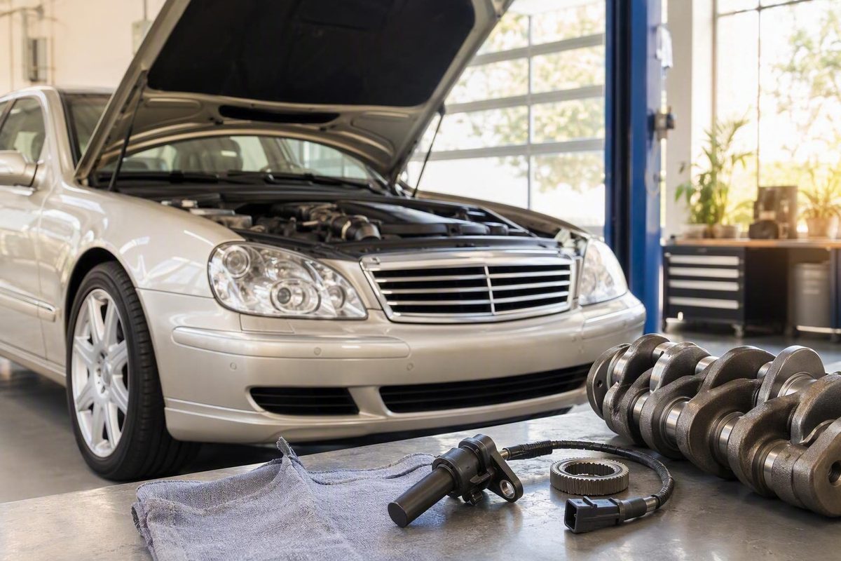
P0335 at a glance: what the code means
The standardized diagnostic trouble code is P0335, with a zero after the letter P. “PO335” is a common letter-O-for-zero typo. A scanner may describe the correct code as “Crankshaft Position Sensor ‘A’ Circuit Malfunction.”
P0335 means the engine control module or powertrain control module—ECM or PCM—is not detecting the expected crankshaft-position signal or considers that signal invalid. It is a circuit or signal diagnosis, not a verdict against one component. The code does not prove that the crankshaft position sensor, crankshaft, or controller has failed.
The crankshaft position sensor reads a rotating target commonly called a reluctor, pulse wheel, or tone wheel. As the crankshaft turns, the target changes the sensor output in a predictable pattern. The controller uses that signal to calculate crankshaft speed and position for ignition timing and fuel-injection control. CarParts.com explains the meaning of P0335 and the role of the crankshaft-position signal.
Several failures can prevent a valid signal from reaching the controller:
- The sensor may not generate the correct output.
- Its supply or ground may be missing, where applicable.
- The connector may have poor terminal contact.
- The harness may be open, shorted, damaged, or intermittently disconnected.
- The reluctor or tone wheel may be damaged or incorrectly positioned.
- Mechanical timing or synchronization may be wrong.
- The ECM or PCM may be unable to receive or interpret an otherwise correct signal.
The sensible first response is therefore not “order a sensor.” Instead:
- Note whether the engine is a no-start, stalls, runs poorly, or appears normal.
- Record all stored and pending codes plus available freeze-frame data.
- Watch engine RPM on the scan tool while cranking.
- Inspect the sensor connector, mounting, and accessible harness.
- Identify the sensor design and obtain the correct wiring diagram.
- Test the circuit before condemning the sensor or controller.
That sequence preserves useful evidence and reduces the chance of replacing a good part.
What “sensor A” identifies—and why vehicle details matter
There is no safe universal answer to “Where is crankshaft position sensor A?” The meaning and physical location of “A” must be confirmed for the exact year, make, model, and engine. Do not assume that it means the front sensor, upper sensor, a particular cylinder bank, or even that the engine has multiple crankshaft sensors.
This is especially important when diagnosing a Mercedes-Benz W220. The general P0335 logic in this guide applies, but the available evidence does not establish one W220-specific location, pinout, test threshold, torque specification, or replacement procedure. Those details must come from service information matched to the exact engine and model year.
Do not transfer the following from another vehicle, even if its sensor looks similar:
- Sensor location
- Connector arrangement
- Terminal numbering
- Supply-voltage specification
- Resistance limits
- Expected waveform
- Air-gap specification
- Mounting torque
- Part number
- Relearn or adaptation procedure
A Toyota Highlander forum discussion illustrates the problem. Participants expressed uncertainty about the connector type, location, and correct fitment and recommended confirming the component by VIN rather than trusting conflicting catalog listings. That is a useful cautionary anecdote, but its vehicle-specific location and specifications do not apply universally or to a Mercedes-Benz W220. The Toyota discussion shows why VIN and connector verification should precede parts ordering.
Identify the sensor design before testing
Two broad crankshaft-position sensor designs require different approaches.
Inductive sensors produce an analog signal as the reluctor passes the sensor. Depending on the manufacturer’s procedure, diagnosis may include resistance, generated-signal, and waveform checks.
A resistance test prescribed for an inductive sensor may be meaningless or inappropriate for a Hall-effect design. Hall-effect testing instead focuses on the specified supply, ground integrity, and signal switching. The distinction between inductive analog and Hall-effect digital sensors is described in general P0335 guidance, while individual applications still require vehicle-specific circuit identification. CarParts.com distinguishes the two sensor technologies and emphasizes application-specific diagnosis.
This sensor-type decision must come before connecting a meter. Published resistance and voltage values vary substantially among applications.
Before beginning electrical or replacement work, assemble this vehicle-information checklist:
- VIN
- Model year
- Make and model
- Exact engine designation
- Sensor location and identification
- Connector face or terminal view
- Wiring diagram
- Code-setting criteria
- Sensor design
- Manufacturer resistance, voltage, and waveform specifications
- Specified sensor-to-target air gap, if applicable
- Mounting and fastener torque
- Applicable technical service bulletins
- Superseded sensor or connector part numbers
- Battery-disconnection instructions
- Any crankshaft-position variation relearn or other calibration requirement
If these details are unavailable, stop before applying voltage, probing terminals, measuring resistance, or ordering a sensor.
Symptoms and the decision to stop driving
P0335 does not produce an identical symptom pattern on every vehicle. Possible symptoms include:
- Check-engine light
- Extended cranking
- Intermittent hard starting
- Complete no-start
- Sudden stalling
- Rough or unstable idle
- Hesitation
- Bucking or stumbling
- Misfire-like behavior
- Reduced power or poor acceleration
A vehicle may show several symptoms, only one, or no obvious drivability problem beyond the warning light. Manufacturers use different code-setting criteria: one controller may set P0335 when no signal appears during cranking, while another may react to signal loss during operation or to an abnormal pulse pattern.
Use the vehicle’s current condition to decide what happens next.
If the engine will not start
Record whether the starter turns the engine normally, then observe live RPM data during a cranking attempt. Also record system-voltage codes and any crankshaft, camshaft, or timing-correlation codes.
A no-start with no plausible cranking RPM makes loss of the crank signal a strong diagnostic direction, but it does not identify the failed component. The sensor, connector, wiring, target wheel, mechanical relationship, or controller input may be responsible.
If reaching the sensor or performing the required test would involve unsafe access or major disassembly, arrange professional diagnosis rather than improvising. General P0335 guidance recommends professional help when access is difficult or the fault remains after basic checks. A-Premium’s diagnostic overview identifies difficult access, reluctor concerns, and recurring codes as reasons to escalate the work.
If the engine stalls or runs severely poorly
Do not continue driving a vehicle that stalls unpredictably, loses power without warning, runs severely poorly, cannot maintain road speed, or may not restart after being switched off. Arrange safe recovery rather than attempting to drive through an active failure. P0335 guidance from Edmunds advises against driving because an affected vehicle may stall unexpectedly or fail to start. Edmunds also lists no-start, rough idle, stalling, hesitation, and reduced acceleration among the possible symptoms.
A brief improvement after restarting does not establish that the fault is gone. An intermittent signal problem may return under the same operating conditions.
If the vehicle appears to run normally
A stored or intermittent P0335 still deserves prompt diagnosis. A presently normal idle and one plausible live-RPM reading do not establish that the circuit remains healthy under the conditions that originally triggered the code.
Record the scan data before clearing anything. Until the cause is known, avoid relying on the vehicle for a journey on which a stall or failure to restart would create a serious problem. The same general no-driving guidance applies if stalling, power loss, or unreliable restarting develops. Edmunds advises addressing P0335 because of the possibility of unexpected stalling or a no-start.
Possible causes: build a fault tree, not a shopping list
P0335 has several diagnostic branches. The evidence does not establish one universally most common cause, so a fault tree is more useful than a ranked shopping list.
Sensor branch
The crankshaft position sensor may be:
- Internally open or shorted
- Producing a weak, distorted, or intermittent output
- Physically cracked or damaged
- Contaminated by oil, debris, or metal particles
- Loose or incorrectly seated
- Installed with the wrong gap or spacer
- Incompatible with the vehicle
- Incorrectly cataloged for the engine
- Defective despite being newly installed
A static result may not represent sensor behavior under every operating condition. Conversely, a result outside a generic internet range proves little if the specification or test method does not match the sensor design.
Connector branch
Connector problems can interrupt an otherwise healthy sensor signal. Look for:
- Green or white corrosion
- Water intrusion
- Oil inside the connector
- Bent, recessed, or damaged pins
- Female terminals with poor contact
- Terminal spread
- Pin pullout
- A broken lock or secondary retainer
- A connector that appears attached but is not fully seated
- Poor previous repairs
A connection may work during a stationary inspection yet fail when operating conditions change.
Harness branch
The harness may contain:
- An open circuit
- A short to ground
- A short to power
- A short between sensor circuits
- Chafed insulation
- Heat damage
- Oil contamination
- Rodent damage
- A weak splice
- Damage near an engine bracket
- Contact with a moving component
- An internal break beneath apparently intact insulation
Pay particular attention to the section leaving the sensor, bends near clips, places where the loom crosses a bracket, and areas disturbed during recent repairs. Recent work is a reason to inspect the area; timing alone does not prove that the work caused P0335.
Signal-target branch
The sensor cannot generate the expected pattern if the target it reads is defective. Depending on the engine, possible target faults include a reluctor, tone wheel, or pulse wheel that is:
- Cracked
- Dirty or contaminated
- Loose
- Bent
- Missing or carrying damaged teeth
- Shifted from its intended position
- Installed incorrectly
- Too far from the sensor
Some targets are easy to inspect. Others require waveform analysis or substantial disassembly before their condition can be confirmed.
Mechanical branch
Mechanical timing and synchronization faults belong later in the diagnostic process unless related symptoms, repair history, codes, or waveform evidence point in that direction. Possibilities include a timing-belt or timing-chain fault, a shifted keyway, incorrect engine assembly, or an abnormal relationship between crankshaft and camshaft signals.
Do not infer a broken belt, chain problem, or internal engine failure from P0335 alone. Mechanical investigation becomes more persuasive when a crank signal exists but its pattern or relationship to the camshaft signal is wrong.
Controller branch
An ECM or PCM problem is possible, including:
- A failed crank-signal input circuit
- Controller power or ground problems
- Connector damage at the module
- Software or calibration issues
- Internal hardware failure
The controller is nevertheless a diagnosis of exclusion. Replacing it solely because P0335 is stored skips the more accessible signal path between the rotating target and the module. A commercial ECM supplier’s diagnostic sequence likewise places module verification after scan-data, circuit, and connector checks rather than treating P0335 as automatic proof of controller failure. Its P0335 overview conditions reprogramming or replacement on testing that identifies a module problem.
First diagnostic pass: codes, freeze-frame data, and cranking RPM
The first pass should collect evidence without disturbing the fault.
1. Record all scan data
Before clearing anything, record:
- Stored codes
- Pending codes
- Permanent codes, if supported
- Freeze-frame data
- Code status
- Engine speed
- Coolant temperature
- System voltage
- Vehicle speed and load, where available
Look for related crankshaft, camshaft, timing-correlation, misfire, or circuit codes. They may help define the failure, but there is no universal rule that one must always be diagnosed first. Interpret the codes together using the vehicle’s code-setting information.
Do not erase P0335 merely to see whether it returns until the original data has been preserved. Clearing it may remove clues about whether the fault occurred during starting, after warm-up, at road speed, or under a particular load.
2. Define when the problem happens
Ask:
- Does the fault occur only while cranking?
- Does it happen after a hot soak?
- Does the engine stall only after warming up?
- Does it occur over bumps?
- Is it more likely in wet conditions?
- Does moving the accessible harness affect it?
- Did it begin after engine, transmission, starter, or harness work?
- Does it appear during normal running without symptoms?
The pattern helps direct inspection.
3. Check live RPM while cranking
With the scan tool connected, watch engine RPM during cranking.
Zero or implausible cranking RPM: The controller may not be receiving a usable crankshaft-position signal. This does not prove that the sensor is defective. Continue with connector, harness, sensor-specific circuit, target-wheel, and controller-input checks.
Plausible cranking RPM with P0335: The signal may be intermittent, distorted, out of synchronization, or present now but absent when the code set. Review freeze-frame data, related codes, code-setting criteria, and signal quality.
Intermittent P0335 on a normally running vehicle: One snapshot showing normal RPM is not a clean bill of health. Where an appropriate and safe vehicle-specific procedure exists, test under the temperature or operating conditions associated with the failure and watch for data dropouts.
AutoZone’s general diagnostic guidance likewise begins with scan-tool RPM information and inspection of the sensor, wiring, and connections before escalation to waveform testing. Its P0335 guide also emphasizes that the code does not prove that the crankshaft itself is defective.
It cannot independently distinguish a failed sensor from a poor connection, damaged target, or controller-input problem.
Inspect and test the circuit in the correct order
Begin with close inspection. Visible or physical evidence can reveal faults that a basic meter check may miss, while unnecessary disconnection can disturb an intermittent problem.
Inspect the mounting, connector, and harness
With the ignition off and the vehicle secured according to the manufacturer’s procedure, inspect for:
- A cracked or loose sensor body
- Incorrect seating or visible misalignment
- Oil, dirt, debris, or metal contamination
- A loose or missing fastener
- A connector that is not fully locked
- A broken locking tab
- Water or oil inside the connector
- Bent, corroded, spread, or recessed terminals
- Pin pullout at either side of the connection
- Cut, burned, swollen, or abraded insulation
- Harness contact with brackets or moving components
- Heat damage
- Rodent activity
- Non-original splices or repairs
- A loom pulled tight by previous work
Do not use improvised methods to probe or manipulate connector terminals. Follow the vehicle manufacturer’s connector-testing procedure and use the specified terminal tools. If the correct method or terminal identification is unavailable, leave connector-level testing to a qualified technician.
A cold, stationary continuity result may not explain a fault associated with temperature, vibration, moisture, or harness movement. Test under the relevant condition only where the manufacturer’s procedure and available equipment permit it.
Use the wiring diagram before the meter
The diagram should answer four questions:
- Is the sensor inductive or Hall-effect?
- Which terminals are signal, supply, ground, or paired sensor leads?
- Where do the circuits terminate at the ECM or PCM?
- Are there intermediate connectors, shared grounds, shielding, or splices?
Use only approved connection and probing methods. Do not assume terminal functions from wire count, wire color, or a diagram for another engine.
Testing an inductive sensor
For a confirmed inductive design, the high-level diagnostic path is:
- Isolate the sensor as directed by service information.
- Compare resistance with the manufacturer’s specification if resistance testing is prescribed.
- Check for unintended connections to ground or other circuits where required.
- Measure the generated signal during cranking using the specified method.
- Inspect the waveform if amplitude, pulse spacing, or intermittent dropout remains uncertain.
Do not use a universal resistance or AC-voltage range.
Testing a Hall-effect sensor
For a confirmed Hall-effect design:
- Verify the specified supply at the correct terminal.
- Verify ground integrity using the manufacturer’s procedure.
- Check whether the digital signal switches correctly during cranking or operation.
- Confirm that the output reaches the controller without distortion or dropout.
Correct supply and ground also do not prove that the sensor produces a valid output or that the output reaches the ECM.
Understand what basic tests cannot prove
Resistance alone does not validate every sensor design. It is meaningful only when the manufacturer prescribes that test for the identified sensor and specifies the terminals and conditions.
Supply voltage alone proves neither sensor operation nor signal delivery. The circuit can have supply voltage while the sensor produces no valid output or the signal path to the controller remains defective.
A normal reading at one moment does not eliminate an intermittent fault. The original failure may depend on conditions not present during the test.
A Mazda forum thread reproducing application-specific diagnostic information illustrates the broader sequence: check sensor output, connector condition, open and short circuits, pulse-wheel condition, and recurrence after repair. Its resistance values, terminal numbers, thresholds, and location are Mazda-specific and must not be applied elsewhere. The Mazda discussion is useful for its diagnostic order, not as a source of universal test specifications.
When to use an oscilloscope
Escalate to oscilloscope testing when:
- Visual inspection finds no fault.
- Correct basic circuit checks pass.
- The problem is intermittent.
- Live RPM drops out unpredictably.
- Signal amplitude or pulse shape is uncertain.
- A damaged reluctor tooth is suspected.
- Crank-to-cam synchronization must be evaluated.
- Mechanical timing or incorrect engine assembly is possible.
In a vehicle-specific expert exchange involving a rebuilt engine, the proposed next steps included comparing crank and cam waveforms and investigating timing and the tone wheel rather than immediately replacing the controller. The case did not establish a final repair, but it illustrates when waveform analysis becomes appropriate. The exchange outlines scope-based escalation after basic wiring checks failed to explain P0335.
Scope interpretation requires the correct connection method, time scale, expected pattern, and preferably a known-good reference. Without those, professional testing is more useful than collecting an uninterpretable waveform.
When P0335 returns after replacing the sensor
Replacing the sensor does not repair a connector, harness, target-wheel, mechanical-timing, or controller fault. If P0335 returns, resume diagnosis rather than automatically installing another sensor.
Verify the replacement part
Check the part number against the exact VIN and engine. Compare:
- Connector keying
- Terminal count
- Sensor length
- Mounting flange
- Tip shape
- Seal arrangement
- Superseded part number
- Electrical design
Visual similarity does not establish electrical compatibility.
In one 2007 Infiniti M45 forum case, P0335 and drivability symptoms reportedly remained after an aftermarket sensor was installed but disappeared after a Nissan-branded replacement was fitted. That outcome supports an incorrect or defective first replacement in that individual vehicle; it does not prove that original-equipment sensors are always required or that aftermarket sensors generally fail. The resolved Infiniti thread is useful only as a vehicle-specific example of replacement-part verification.
Verify installation
Confirm that the sensor is:
- Fully seated
- Mounted in the correct orientation
- Tightened to the vehicle-specific torque
- Sealed as specified
- Positioned at the specified air gap
- Installed with any required spacer
- Free from debris beneath its mounting surface
Do not assume that every seal should receive the same treatment, every sensor is self-spacing, or every vehicle requires a relearn. Follow the exact procedure for the application, including battery-disconnection and calibration instructions where specified.
Reinspect the connector and harness
Sensor replacement can move an already damaged wire or disturb a weak terminal. Recheck:
- Female-terminal condition
- Corrosion inside the connector
- Water intrusion
- Pin pullout
- Broken connector locks
- Harness strain
- Damaged splices
- Internal breaks near the plug
- Chafing between the sensor and controller
- Controller-side connector condition
If the manufacturer’s procedure permits end-to-end testing, compare the signal at the sensor with the signal arriving at the controller. A correct sensor output that becomes defective before reaching the ECM directs attention to the harness and intermediate connections.
The Mazda forum discussion provides a bounded example: sensor replacement did not resolve every reported P0335 case, and one participant reported that an intermittent shutdown stopped only after a damaged section of sensor harness was replaced. That owner report is not universal proof, but it reinforces the need to inspect the full circuit rather than repeatedly replacing the sensor.
Move to the target and mechanical relationship
If the replacement sensor is verified, correctly installed, and producing the expected output—and the circuit delivers that signal to the controller—inspect the reluctor or tone wheel. Look for damage, looseness, contamination, incorrect positioning, or abnormal air gap.
Where direct viewing is difficult, waveform analysis may reveal a repeating missing or malformed pulse before disassembly. Comparing crankshaft and camshaft signals can then help determine whether the problem is electrical, target-related, or mechanical.
Leave the ECM or PCM until last
Controller diagnosis should come after demonstrating that:
- Controller power and grounds are correct.
- The proper sensor is fitted.
- The sensor has the required supply and ground, where applicable.
- The sensor generates the correct output.
- The signal reaches the controller.
- Connector terminals are secure.
- The target wheel is sound.
- Relevant mechanical timing is correct.
- Applicable software or bulletin checks have been completed.
Only then does controller-input failure become a defensible conclusion.
Repair choices and proof that the fault is fixed
The correct repair is the one matched to the demonstrated fault.
Possible repairs include:
- Cleaning or replacing damaged connector terminals
- Replacing a broken connector housing
- Repairing an open, shorted, chafed, or heat-damaged harness
- Correcting a weak or corroded splice
- Installing a verified crankshaft position sensor
- Correcting sensor seating, orientation, or air gap
- Repairing or replacing a damaged reluctor or tone wheel
- Correcting a confirmed timing or synchronization fault
- Updating, repairing, or replacing the controller after proof of controller failure
Avoid universal replacement instructions. Sensor access, mounting torque, air gap, battery precautions, seal treatment, and relearn requirements vary by application.
What is reasonable DIY work?
For a careful owner with the correct tools and vehicle-specific information, reasonable DIY work may include:
- Retrieving and recording codes
- Saving freeze-frame data
- Observing cranking RPM
- Conducting an accessible visual inspection
- Checking connector engagement
- Identifying visible harness damage
- Performing manufacturer-specified basic circuit checks
- Verifying the replacement part number and installation
Stop when a test requires uncertain terminal identification, improvised probing, difficult access, waveform interpretation, or substantial disassembly.
Professional help is appropriate when:
- The engine stalls unpredictably.
- Access cannot be achieved using the specified equipment and procedure.
- The fault appears only under temperature or vibration conditions.
- Oscilloscope analysis is needed.
- The reluctor wheel is difficult to inspect.
- Mechanical timing is suspected.
- Major disassembly is required.
- P0335 returns after a correctly verified repair.
- Controller programming or replacement is being considered.
Post-repair verification checklist
After completing the repair:
- Reconnect all components and inspect the work area for disconnected grounds or unsecured harnesses.
- Clear the code only after the repair is complete.
- Start the engine and confirm plausible live RPM.
- Perform several shutdown and restart checks.
- Recreate the condition associated with the original fault where the vehicle-specific procedure permits it.
- Monitor related crankshaft, camshaft, voltage, and misfire data supported by the scan tool.
- Check for stored and pending codes.
- If the vehicle is safe to operate, perform a controlled test drive that recreates the original conditions.
- Scan again after the drive.
- Confirm that the original symptoms and P0335 remain absent.
Clearing the warning light is not proof of repair. A successful repair means the engine starts and runs correctly, relevant data remains plausible, the original failure conditions no longer reproduce the problem, and P0335 does not return as stored or pending.
Frequently asked questions
Does P0335 mean I need a new crankshaft position sensor?
No. P0335 means the ECM or PCM did not receive or accept the expected crankshaft-position signal. The sensor is one possible cause, but the connector, harness, applicable power or ground circuits, reluctor wheel, mechanical synchronization, installation, or controller may be responsible.
Check scan data, cranking RPM, the connector, and the harness before buying a sensor. Identify the sensor design and use the vehicle-specific test procedure before authorizing replacement.
Can I drive with a P0335 crankshaft position sensor circuit code?
Do not continue driving if the engine stalls, loses power unpredictably, runs severely poorly, or may not restart. Arrange recovery and diagnosis instead.
If the vehicle currently runs normally and P0335 is stored or intermittent, diagnose it promptly. Normal operation at that moment does not guarantee that an intermittent signal fault will not recur.
Why does my scanner show P0335 when the engine still runs normally?
The signal may have failed briefly, fallen outside the controller’s expected pattern, or recovered before you checked it. The fault may depend on temperature, moisture, vibration, harness movement, or a particular phase of starting or running.
Freeze-frame data and pending-code status may help establish when the event occurred. A normal live-RPM reading now shows only that the controller sees plausible engine speed at that moment.
What should I check if P0335 returns after replacing the sensor?
Verify the part number and connector configuration for the exact VIN and engine. Confirm that the sensor is fully seated and installed with the specified gap, spacer, seal treatment, torque, and relearn procedure, where applicable.
Then inspect connector terminals, locks, corrosion, water intrusion, pin pullout, damaged splices, and harness breaks—especially near the sensor and in areas disturbed during replacement. If the part, installation, circuit, and sensor output are correct, inspect the reluctor wheel and mechanical synchronization. Consider the ECM or PCM only after the complete signal path and relevant mechanical conditions have been verified.
Do I need an oscilloscope to diagnose P0335?
Not always. Code retrieval, freeze-frame review, cranking-RPM observation, visual inspection, and correct basic circuit checks can identify many faults.
An oscilloscope becomes valuable when basic checks pass, the fault is intermittent, signal quality is uncertain, or crank-to-cam synchronization and reluctor condition must be assessed. It can reveal dropouts and malformed pulses that a multimeter or continuity check may not show.
The essential lesson is to diagnose before replacing. P0335 is evidence that the ECM or PCM lost or rejected the crankshaft-position signal, not proof against one component. Preserve the scan data, check cranking RPM, identify the sensor design, inspect the connector and harness, and follow vehicle-specific circuit specifications before moving to waveform, reluctor-wheel, timing, or controller diagnosis. If stalling, severe poor running, unsafe access, or an unreliable restart is involved, choose recovery and qualified diagnosis—not continued driving or another unverified part.